Latest posts
Arriving at the van der Corput sequence
Domagoj Pandza on January 10th, 2018
Mathematics
Show in single article view

The van der Corput sequence is the lowest discrepancy sequence known to exist. It was brought forward by one Johannes Gaultherus van der Corput in 1935 and is remarkably simple in implementation as it is a transformation of the sequence of natural numbers, where each element of the latter is reflected around the radix point. The original paper is inaccessible due to old age and even when one jumps over that digital wall, there are language barriers as van der Corput was Dutch.

Equal shares

It's only fair

If you're not familiar with discrepancy, it's the best known measure of non-uniformity of sequences which also happens to be extremely hard to compute for any non-trivial sequence (which is to say, any useful one). To say a sequence is uniformly distributed is to say that any subinterval of the interval on which the sequence is defined receives an amount of elements that is proportional to the relative length of the interval.

On the notation used

When it comes to notation, as sequences are ordered, we morph notation used for tuples which are also ordered. Nominally, it's \( (x_i)_{i\in\mathbf{N}} \), but some prefer to use curly braces. As we mentioned, sequences can be defined as functions which map from the domain of integers to the codomain of sequence elements (essentially, indices to objects). Which is to say \( (x_i)_{i\in\mathbf{N}} \) is a fancy way of writing \( S(i \mid i\in\mathbf{N} ) = x_i \). The \(x_i\) is merely a placeholder for something actually useful.

One such trivial example of a uniformly distributed finite (and seemingly useless) sequence defined on the \([0,1)\) interval could be easily constructed by taking the desired number of points \(N\) and using it in the definition as \( (i/N)_{i=0}^N \) which will give us an evenly spaced point set that for \(N=10\) looks like:

$$ \begin{split} (i/10)_{i=0}^{10} & = \left( 0, \frac{1}{10}, \frac{1}{5}, \frac{3}{10}, \frac{2}{5}, \frac{1}{2}, \frac{3}{5}, \frac{7}{10}, \frac{4}{5}, \frac{9}{10} \right) \\ & = \left( 0, 0.1, 0.2, 0.3, 0.4, 0.5, 0.6, 0.7, 0.8, 0.9 \right) \end{split} $$

Consider the subinterval \([0, 0.1)\) which is a tenth of the full interval's length (measure) on which the sequence is defined. It receives exactly a tenth of all the points (of which there are \(10\) in this case). Perfectly uniform, trivial and utterly useless... Why? First of all, it's finite due to its dependence on the number of elements in a sequence. Second of all, it's implicitly ordered in ascending order, meaning that elements come off the "queue" predictably, consider the first four elements of the sequence separately:


As expected, the upper half of the unit interval is completely devoid of elements at this point, making this a very uninteresting sequence to draw any kind of samples. Not to mention it is finite and depends on the number of points. But it is uniformly distributed, so it might be worth investigating it further. We do want our infinite sequence to be as uniformly distributed as possible. We've been looking at in the compact decimal encoding, but let's go to the "higher granularity representation" of the binary encoding (naturally, you could also choose octal or even ternary to see the same thing) and, for convenience, change \(N\) to \(8\) because a power of \(2\) in the denominator can have exact fraction representation (consider \(0.1_{(10)} \approx 0.0001100110011001101_{(2)} = 0.1000003814697265625_{(10)}\)):

$$ \begin{split} (i/8)_{i=0}^{8} & = \left( 0, 0.125, 0.25, 0.375, 0.5, 0.625, 0.75, 0.875 \right)_{(10)} \\ & = \left( 0.000, 0.001, 0.010, 0.011, 0.100, 0.101, 0.110, 0.111 \right)_{(2)} \end{split} $$

Notice how the most significant bits of the fraction are the least changing ones as the sequence progresses in order. Now notice what happens when we flip those bits, making the high frequency less significant bits switch places with the low frequency higher significance bits:

$$ \begin{split} (i/8)_{i=0}^{8} & = \left( 0.000, 0.001, 0.010, 0.011, 0.100, 0.101, 0.110, 0.111 \right)_{(2)} \\ & \rightarrow \left( 0.000, 0.100, 0.010, 0.110, 0.001, 0.101, 0.011, 0.111 \right)_{(2)} \end{split} $$

Take a look how the first four elements seed the unit interval:

As you can see, much better coverage of the unit range. Again, if you look at the flipped bits, you'll notice that they're merely natural numbers in binary form reflected around the radix point, as shown in these examples: \(1_{(2)} \rightarrow 0.1_{(2)}, 10_{(2)} \rightarrow 0.01_{(2)}, 11_{(2)} \rightarrow 0.11_{(2)}, 100_{(2)} \rightarrow 0.001_{(2)}\)... This allows us to define the van der Corput sequence, without any dependence on \(N\) (thus infinite), as:

$$ \left( \sum_{k = 0}^{\log_2(i)+1}{d_k(i)2^{-k-1}} \right)_{i\in\mathbf{N}} $$

Where \(d_k(i)\) retrieves the \(k\)th digit for the reflection. Does the new sequence retain its uniform distribution? While we have no idea what is its exact discrepancy even in 2018. (or the discrepancy of any other non-trivial sequence) as it is extremely hard to compute, van der Corput and countless others have been working hard on providing a progressively decreasing upper bound on its deviance. Since its introduction in 1935., it is still the lowest discrepancy sequence in its class.

Many generalizations have been invented since in hopes of beating it, but also ones that make use of it in higher dimensions such as the Halton sequence. Given its low discrepancy results in great coverage of the domain and the associated random appearance, van der Corput sequence values are often called subrandom or quasirandom numbers and are extremely useful in many fields as a deterministic substitute for random values drawn from a uniform distribution, for example, Monte Carlo integration. I personally use the van der Corput sequence and its derivatives to solve a multitude of problems spaning anti-aliasing, terrain generation and realtime global illumination.
DWM, DXGI, swap chains, latency, throughput and you
Domagoj Pandza on March 12th, 2017
Computer Graphics
Show in single article view

Important caveat

Everything in this article is predicated on the assumed lack of hardware support for variable refresh rates which enable "hassle-free tear-free" experiences. This includes technologies like Nvidia's GSync and AMD's open-ended Freesync. While increasingly available, I still consider such displays to be in the enthusiast department and, as a developer, the only way to provide a tear-free experience without it is with an implementation that understands how Vsync works. If image quality matters to you or your customers. For this article, we assume a run-of-the-mill 60 Hz display.

Properly configuring and handling a swap chain is crucial to ensuring a responsive and pleasant interactive application. Whether you're developing a digital content creation tool, video playback software, simulation or game which requires fluid controls, there's a lot to configure in order to ensure smooth sailing. Unfortunately, rich options and poor documentation often mix poorly and result in mediocre performance, bordering on bad. This is further exacerbated by the lack of a silver bullet configuration, as each application has its own specific needs which map it to a different location on the throughput-latency trade-off chart.

A lot of the information in here is platform agnostic and applicable everywhere. However, the article is written from the perspective of a Windows desktop developer utilizing DWM, DXGI and DX APIs, handling all the caveats the majority platform entails. It is, however, not a tutorial and there is no hand holding.

Things have changed

For the better

Exclusive fullscreen mode, in the traditional sense, is gone in Windows 10. People are still polarized on the subject, I personally find it to be a step in the right direction. Anyone who owns a multi-display setup sighed in relief when they first noticed that Alt+Tab no longer resulted in epileptic blinking due to mode switching. Who could forget the agony of having your system gamma settings messed up or games crash after switching to another application because they weren't programmed to recover from an unsolicited mode change instigated by being put in the background. A game is an application like any other and the experience should be as smooth, if not smoother.

Due to ISV disagreement during the development of DirectX 12 (and DirectX Graphics Infrastructure which made it possible), Microsoft added an "immediate" mode which I'd recommend you avoid and always aim for a borderless window. We will not be discussing it here. We will also not be discussing VR as most people don't care about this at the time. In the future, it might warrant an article of its own. Same goes for variable refresh rate display technology.

So, why isn't everyone onboard? Everything on Windows 10 is presented to the screen solely through the compositor, a key component of the Desktop Window Manager. To ensure there is no tearing when presenting a buffer to the display, the swap happens exactly at the time of a vertical blanking of the screen (usually, every 16.67 ms). A non-negotiable* V-Sync. Unfortunately, somewhere along the way bad programmers happened and introduced a massive amount of input lag by misunderstanding how the swap chain behaved with V-Sync enabled which started a decades long prejudice against V-Sync among gamers, all thanks to a few popular, but technically inept games.

Gamers disabled it altogether and lowered settings to a point where they could consistently hit 200 frames per second. They ignored the screen tearing and the drop in rendering quality because it gave them a spring in their step in-game as all the unnecessarily computed frames were just discarded and the latest one was used, holding their newest inputs. As a developer using fullscreen exclusive mode, you didn't have to justify yourself to DWM, you would just say: "Here's the fresh buffer, read from it, I don't care if you were in the middle of another buffer." And... It's gone. Someone's bound to be upset.

The root of V-Sync prejudice

Spoiler alert: It's people being bad at computers

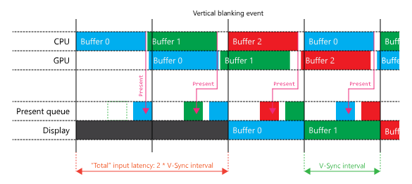
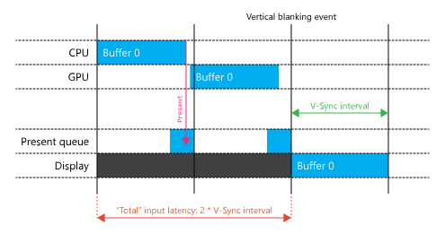
Why do some games have ridiculous input lag with V-Sync enabled, even when they complete frames in less than 16 ms? Generating a frame for any modern game running on a computer with recommended specs does not actually take less than 16.67 ms, no matter what the Steam FPS overlay tells you. The GPU time tells only a part of the story. CPUs are required to read inputs, update state and then define, encode and enqueue all the work that needs to be peformed subsequently on the GPU to get a complete frame to present to the screen. Optimally, this happens in less than 16.67 ms. So, if you were to press the move key right now in an optimal game (CPU time: 16ms, GPU time: 16ms), in the best case scenario your changes would be registered in just over 33 ms, hitting the (relative) second vertical blanking event provided that the CPU work began at exactly after the last vertical blanking event. To understand this a bit better, let's start "at the bottom" and work our way up.

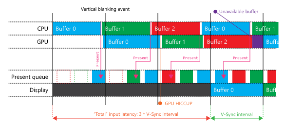
With the approach outlined in the example diagram above, the CPUs are yawning while the GPU is filling Buffer 0. The solution to this is to introduce pipelining. The CPUs can begin work on a new frame immediately after a present is queued (implicitly by calling IDXGISwapChain1::Present1). This doesn't reduce latency, but it does increase throughput. Until now, we have only allowed a single present to be queued, hence why the CPUs didn't start working on the next frame immediately. This is the implicit minimum frame latency of 1. To allow for pipelining, we need to allow for at least two presents to be queued (our maximum frame latency) and match the numbers of available back buffers. Otherwise, we'd have to wait on a surface to become available. By default, which is what a lot of people use, the maximum frame latency is 3. We don't necessarily have to hit all 3 presents, these settings are there to ensure a smooth framerate at the expense of latency when hiccups happen. Hiccups are a result of deviations in CPU and GPU times combined with the shifting phase of CPU work with respect to a blanking event, incurring a miss of the next vertical blanking event as demonstrated in the image below.

While this has been neatly set up to happen right at the start for demonstration purposes, this will happen. The phase of CPU work with respect to vertical blanking events changes every frame and both CPU and GPU workloads vary from frame to frame, a third present will eventually find its way into the queue and demand its time on the screen. After that happens, it is highly unlikely a three frame latency will be undone (and even if it were, it would just happen again). Which increases your average baseline input latency to just over 50 ms. Furthermore, if a buffer is being used on screen, the GPU cannot proceed to work on it. This results in the GPU having gaps in the timeline as it delays work beyond the next blanking event, when the current front buffer's time is up. You might be thinking: "I'll just have 3 back buffers and that will fix it." That would actually only make things worse. Once the present queue is full, you will be able to encode the next frame, but once you inevitably attempt to present, you will cause a block inside of IDXGISwapChain1::Present1. It waits until the queue is reduced by one (next vertical blanking) and then inserts it at the end, returning back to user code. This vicious cycle would continue with frames constantly queueing after blocking, earning you an additional 16.67 ms latency penalty for a grand total of just over 66 ms on average.

50-60 ms is the usual input latency incurred by misunderstanding swap chains (usually leaving them on default), and that's when you're aiming at a compute budget that is less than 16 ms on both the CPU and the GPU. Games that are locked to 30 FPS (budget being 32 ms for each), you usually get more than double the latency. And this is just your baseline, self-inflicted input lag. On top of all this, there is the constant 60-80 ms latency of having the actual image transmitted and displayed on the screen. Console gamers have been living with latency reaching 200 ms for years. Most PC gamers feel comfortable with latency being around 100 ms, although they have no idea it's actually so high, they gauge it by feeling it. In the next section, we discuss how to bring baseline input latency down to 33 ms for games aiming at 60 FPS games without tearing (or 66 ms if you're going for 30 FPS, nobody's judging.)

Adapting to change

Finding an ideal middle ground

As we touched on in the beginning, Windows took the stance that nobody receives special treatment by default. All applications go to the screen through the DWM compositor, which presents content to the screen at vertical blanking events (a "non-negotiable" default V-Sync). One of the primary complaints about previous OS versions (and associated APIs and runtimes) was the unnecessary surface indirection involved with regular windows where the client area was filled on the GPU because one couldn't just pass a handle to the DX filled, resident surface on the GPU to DWM for composition on the GPU. Naturally, this roundtrip incurred unnecessary latency and had to go. With Windows 8, and more dominantly in Windows 10, this became the legacy model (so called BitBlt presentation model) in favor of a new, more sensible flip model which could directly pass the handle to the freshly minted resident buffer to DWM for compositing, opening the door to proper borderless fullscreen windows. However, one must do a little bit of configuration to get the best results when it comes to responsiveness.

If it hasn't been made abundantly clear until now, V-Sync is now implicit. You don't need to synchronize on any particular interval inside of IDXGISwapChain1::Present1, in fact, the semantics of it are different in the flip model. An interval of 0 indicates to the runtime that it should cancel the remaining time of the previously queued present should the next one finish computing on the GPU before the previous frame's time on screen is up (it could be told to stay on screen for up to $n$ intervals). This combined with a maximum frame latency of 2 enables you to hit up to 120 FPS and latency as low as 17 ms.

Reducing latency involves a few steps, the first one being reducing the maximum size of the present queue to 2 by calling IDXGISwapChain2::SetMaximumFrameLatency. As we've already mentioned, the maximum frame latency is set to 3 by default. Reducing from 3 to 2 will enable us to have a latency of 33 ms or lower, provided we fire off work at optimal times. To actually be able to queue two presents and not wait on a currently presenting front buffer, the swap chain needs to be created with 3 buffers (there is no longer an implicit windowed front buffer which was part of the indirection scheme). Two of the buffers will be always available for rendering while one will be used by DWM for composition.

So, what is the optimal time to start updating state and developing a frame? Right at the last possible microsecond where the CPU part can do its work and finish just before the next vertical blanking event. In practice, when you're releasing a new application, you have a very specific (although open) set of hardware which only has a lower bound defined by minimum hardware requirements at which it is still possible to have an interactive experience. Hardware on which both the CPUs and GPUs will pretty much be doing a lot of work, usually up to 15-16 ms each (or 30-32 ms if you're targeting a low-end console). Thus, the previously discussed optimal time will be around a vertical blanking event, so you might as well have the system wake you up to prepare the next frame once it happens, unless there are open slots in the present queue in which case it will call you immediately. This is demonstrated in the image below.

This is achieved in code by creating your swap chain with the DXGI_SWAP_CHAIN_FLAG_FRAME_LATENCY_WAITABLE_OBJECT flag, which is also a prerequisite for setting frame latency on the swap chain. This enables you to sleep on an associated, cleverly titled "waitable object" which only wakes you up at the optimal times described in the previous paragraph. The idea is that you're not supposed to be running a busy loop which would constantly start too soon or too late, incurring additional latency. You can invent this on your own, though. There is no magic to it, just track your timings carefully and sleep based on them.

And that's all there is to it, keeping it simple in the face of too many options. I implore you to give this a try, you will find a surprisingly nimble mouse and keyboard with no sacrifice in image quality. Until next time!

Understanding the need for memory barriers in multithreaded systems
Domagoj Pandza on July 8th, 2016
Programming
Show in single article view

Memory barriers are often confusing to people, newbies and consummate professionals alike. I reckon it is because most people learn that they need to use memory barriers but seldom go the extra kilometer of finding out why they're needed and what they're abstracting. Sure, they know that it is to prevent memory reordering but not why the reordering happens in the first place. As such, questions about memory barriers are brought up often in programming social circles.

This would be fine if it were possible to explain the nuances succinctly in a chat room inhabited by people with varying degrees of expertise on the subject, all generating noise in the communication channel. It isn't. And more often than not, I get annoyed by people butchering it. My goal here is to take a people on a tour and hopefully have a linkable resources by the end of it. But to get to get to the heart of this story, we've got to go back to the beginni— we've got to make sure your understanding of CPU caches is not merely "the stuff that hides main memory latency through black magic".

For whom it may concern

I know it's a little bit late, but I am the worst combination of busy and lazy. As an apology, I went a little above and beyond. If you need further clarification, @ me on chat.

Let's make sure we map to the same page

Otherwise, this article won't be very cache-money.

A cache is any construct which stores often needed resources in a quickly accessible manner, resources which would otherwise be temporally prohibitive to continually obtain from a backing store on an individual basis. While most of us are used to thinking about them in the context of software and hardware, the notion is based on real world caches which expire. Everyone has a cache. I have one on my desk, a miniature trash can filled with sour Skittles obtained from a local store called Plodine. As I often reach for them, buying them in spades from the store enables me quick access to them as long as they're not depleted, after which another roundtrip is needed.

A cache of Skittles ready for prompt consumption

Computer caches, on the other hand, are quick access staging areas for data and instructions. They do not expire unless instructed to do so and the system has a responsibility to propagate changes in both ways, from the caches to the comparatively slow main memory and vice versa in order for the state not to become corrupted or stale. Every load and store needs to be sanitized and checked for consistency which can be guaranteed by following carefully designed protocols to the letter (which computers are extremely good at).

In order to avoid diminishing returns, caches are never made too large. Multiple levels of cache are used instead, progressively increasing in size (and access times). This requires additional bookkeeping, but nets the best returns. Each respective level's size seldom changes. In fact, Intel hasn't changed the size of the first two levels of cache in over 10 years. They're actually on the brink of doing so with the next-gen Ice Lake architecture, increasing combined L1 cache to 80 KiB (data-biased, 3:2) and L2 to 512 KiB.

The architecture of a CPU cache reflects its purpose. Given its function is to be a buffer between the CPU and main memory, accessing it must be fast and a direct function of memory address. Thus, a CPU cache needs to be designed like a hardware hash table. And for the most part, that is exactly what it is. Furthermore, given that accesses in memory are more often than not localized, access granularity for a cache shouldn't be too small. Every time a fresh bit of memory is touched, it is desirable to take out an aligned swath, known as a cache line. The choice of size is not an easy one, but Intel has settled on using 64 bytes for their desktop products ever since Pentium IV. A single cache line is augmented with necessary metadata such as flags and tags. Thus, physically, caches are larger than their logical description for the purposes of internal bookkeeping.

As the cache gets populated (not even necessarily filled up to capacity), due to its design as a fixed-size hardware hash table, conflicts on loads are inevitable. This means that cache lines from conflicting ways need to be sanitized and evicted. Thus, eviction protocols are of paramount importance, especially as data may need to be propagated back to main memory. Other cores may also need to be notified of the eviction.

With all this in mind, a CPU cache is composed out of $n$-sized hash buckets called "sets" where each can thus be inhabited in $n$ "ways" each sufficiently sized to harbor a single cache line. To put this in practical terms, one of my favorite Intel processors of all time, the i7-2600K (which is still alive and kicking in many machines almost a decade later) has an evenly split 8-way set associative 64 KiB L1 cache. $32$ KiB ($2^{15}$ B) are dedicated to data and the size of a cache line, as discussed, is $64$ B ($2^6$ B). In total, it can hold $32768 / 64 = 512$ cache lines. Each set can hold $8$ of these cache lines, thus the number sets is $64$.


Way / Set 0 1 2 3
0x0 0x00000000
0x1 0x00000040 0x10000040 0x20000040
0x2 0x00000080 0x10000080
0x3 0x000000c0 0x130000c0 0x200000c0 0x300000c0
0x4 0x00000100
0x5 0x00000140
0x6 0x00000180
0x7 0x000001c0

As you might imagine, this would be difficult to showcase and reason about here, thus we will be using a fictional, crappy two-core multiprocessor for the duration of this article. It conveniently has only one level of four-way set associative cache per core (eight sets on each), a preview of which you can see above. The complexity of adding more levels of cache is staggering, just consider a decade old processor like the 2600K also has a similarly configured 256 KiB L2 cache per core and a third level of cache, up to 16-way set associative, which is shared between four cores (lending up to 2 MiB to each) and the integrated GPU. Intel refers to it as the Last Level Cache or LLC. Not to mention that cache functionality, interops and even mere addressing rises in complexity with the level of the cache discussed.

Indexing an L1 cache

Sticking to the lowest level, how do we go from a memory address to a slot in the L1 cache? We utilize low bits of the underlying virtual address (prior to translating as the relevant bits remain unchanged by it given the smallest page size is $4096$ bytes). Since we decided on a $64$ byte wide cache line ($2^6$ B), the six lowest significant bits address the data to be shoveled into a specific way of a specific set. Given that we only have $8$ sets in our toy cache, we only need bits $6$-$8$ to determine in which set our cache line lands. In parallel with this, we also translate the virtual address into the physical one and use the tags derived from the upper physical address associated with each "way" to determine which one gets it. Specifically, for the tag bit count we subtract the address width of the cache line itself ($6$ in our case) and the index width ($3$ in our case).

Assuming our processor is 32-bit (because nobody has time to write out 48-52 bits), say we have a memory address of 0x130000c0, bitwise that's 0001 0011 0000 0000 0000 0000 1100 0000. Bits 6-8 are $011$ or 0x3. The "ways" divide the particular indexed set into slots as a function of the tag (which is computed as the remaining $32-6-3 = 23$ upper bits of the translated physical address). In our table, it lands coarsely in way 1 of set 0x3.

Some lingo to keep in mind

Failure to obtain data from the cache is known as a cache miss. It instigates a load of a cache line containing the desired data. Conversely, a cache miss due to a different cache line in the desired slot of a set is sometimes called a capacity miss (even though not necessarily at capacity). A cache miss trying to access a recently evicted line is referred to as an associativity miss.

Duplicating cores means duplicating caches

An obvious, but critical observation

The nuanced dance between all the cores and their local low-level caches is where the complexity arises. Especially when we consider writing data as opposed to simple reading. Making a fast cache for each core is trivial compared to ensuring timely data consistency across multiple cores in a multithreaded environment. We will show how modern cache coherency design introduces the need for memory barriers in order to remain as fast as possible while producing results we deem correct (because the computer doesn't care).

Take, for example, a simple write to the cache by CPU 0. The target cache line might be shared/duplicated by CPU 1. Obviously, you don't write the value to both caches, you just tell (we'll quantify how shortly) CPU 1 to consider its cache line invalid and mark CPU 0's cache line as modifiable. Then we proceed to write our new data. Should CPU 1 need it later on, it will have to request it from CPU 0's cache after suffering a cache miss on its own. You're beginning to see the importance of keeping data coherent across multiple cores and caches. But how exactly is this achieved, especially as multiple threads start manipulating the same data? To cover all the possibilities, the protocols involved are very involved. However, we're in luck as there's only one specific and comparatively simple protocol that directly concerns us for the purposes of this article.

Comic relief

This reminds me of the joke where a man claimed to be quick at arithmetic. When asked what's $18$ times $19$, he espoused $26$ to everyone's bamboozlement. Alas, he said he was quick at arithmetic, not necessarily correct.

The Illinois Protocol

MESI (Modified / Exclusive / Shared / Invalid) protocol, also known as the Illinois protocol, is an invalidation-based cache-coherence protocol compatible with the more performant write-back caches, as opposed to write-through ones. Its name stands for the four states on which it is based.

Each cache line takes one of these states, encoded in an additional two-bit tag associated with it. Following is a short description of the possible states:

  • Modified state is set on any cache line in the cache of a CPU that modified it recently, usually after moving from a Shared state. This means it only exists in that CPU's cache as others received an invalidation order previously. Furthermore, as we're talking about a write-back cache, the CPU is responsible for this data. Either to write it back to the main memory or hand it off to some other CPU's cache (share, then receive invalidation order).
  • Exclusive state is set prior to modification of a cache line. At this point, the data still up-to-date and the CPU itself has no responsibilities towards it yet. In this state, it is accessible only be the CPU in whose cache it is marked as such.
  • Shared state is set on any cache line which is shared across multiple CPUs, in other words, there is at least one copy of it in other CPUs' caches. In this state, it is up-to-date and cannot be modified without ordering the acting CPU's cache line state to exclusive and the remaining ones to invalid.
  • Invalid state is set on any cache line which is currently "open for business", unused. It is preferable to place any new data inside invalid cache lines as others require overhead in the way of MESI state changes communicated between the participating CPUs and their caches. Not that there is much you can do over the choice of set and way, though.

How are these states transitioned? Messages. MESI protocol is a message-passing protocol. The messages themselves are simple, the most important ones being the read and invalidate requests alongside their responses, including the combined read-invalidate message commonly known as RFO / Read For Ownership. And of course, the writeback request which facilitates the timely completion of a CPU's responsibilities to a cache line in the modified state before it gets evicted.

Suppose now we have a cache line in CPU 1's cache which we want to modify by CPU 0 whose own cache line is marked as effectively invalid. By agreement to ensure cache coherency, we cannot write to the cache line until all other CPUs invalidate their copies and send a confirmation to the CPU wanting to modify it, to perform any remaining actions currently in progress. This is wasteful as CPU 0 in this case will stall as it waits for the invalidation confirmation after sending an RFO, especially as it intends to just overwrite the data immediately.

Write policies

A write-back cache doesn't rush to reflect its changes in main memory, data propagation is deferred until a block is being evicted/replaced. A write-through cache synchronously writes both to the cache and the backing memory. Former requires more bookkeeping than the latter.

Enter the store buffer

To this end, store buffers were introduced. Their name is apt, the CPU performs intermediate stores in them while awaiting an invalidation confirmation from other CPUs. This allows the CPU in question to process further instructions without stalling. To avoid reading stale information when acting on its own cache data, the CPU owning the store buffer can also check for updated information waiting to write through and act on it instead. Other CPUs cannot see the contents of their twins' store buffers.

This is what instigates the need for write memory barriers. Some writes which require access to an unowned cache line will be stuck in the store buffer while others whose target cache line is already in the cache (modified / exclusive) will be modified first, even though the instruction came in second (from the perspective of another CPU which cannot snoop other CPUs’ store buffers). The writes are out of order for speed. While the pursuit of speed is great, sometimes you need to slow down to get things right. Most of the time, this doesn’t matter. But when you depend on some variables to be modified in a specific memory order, you need a write memory barrier instruction in place.

In reality, it's actually an attribute on another instruction rather than an instruction itself (but it can be). The CPU with the memory barrier instruction will do two things. First, mark store buffer entries that precede the barrier and are halting the flush (awaiting RFO/invalidation confirmation). Second, prevent any further writes to the cache by any subsequent instruction by buffering those writes as well (unmarked). This will prevent cache writes from going out of order wrt what the programmer expects as, once again, other CPUs cannot see the contents of their twins' store buffers. Once the invalidation confirmations are received, the store buffer is flushed to the cache and changes become visible to other threads, with proper effective order.

"Let's go into invalidation debt!"

On the flip side, hardware designers found another performance loophole to exploit. Instead of actually invalidating the cache line immediately, just go into debt by sending a confirmation immediately. This way, a queue is formed which needs to be cleared before sending any further messages regarding the affected cache lines. This is useful because the CPU might be involved in something more important than invalidating an unused cache line (at that moment). Furthermore, due to physical constraints, the CPU itself cannot check its invalidation queue like it can the store buffer.

What does it mean for the CPU to be in "invalidation debt"? Unperformed invalidations leave its cache in a stale state as it will keep reading data from invalidated cache lines under the impression they're valid. Thus, we need read memory barriers. Read memory barriers ensure that the invalidation queue gets flushed and, in this case, means the CPU needs to stall until this is done as further processing depends on data written by other CPUs to become visible.

Write, read and general memory barriers

This will have undoubtedly placed some moderate pressure on your brain. So, let's recap together. A write memory barrier ensures that every write preceding the barrier is effectively completed before the one superseding it, from the perspective of some other thread (!). This is done by hiding out-of-order writes in the store buffer as unmarked while waiting for invalidation confirmation of the one we want to appear to have been written before. So once all the marked entries have their matching invalidation confirmations received, the entire store buffer is flushed to the cache, ready for other threads to request access to it.

A read memory barrier ensures that writes done by other threads/CPUs are all visible to the invoking CPU/thread by making sure the invalidation queue is empty and offending cache lines are invalidated, forcing loads to request access to up-to-date information after a cache miss.

General memory barriers combine both read and write memory barriers, which is a more complicated operation that is not always required. Hence on most architectures, these instructions are offered individually.